Parent Product: Noralis Integrated Software Environment (NISE)
Short Collar Corrections adjust and provide confidence in azimuth readings when magnetic qualifiers are “out of spec’ due to drill string interference.
Successful application of short collar corrections will decrease the MWD tool’s ellipse of uncertainty.
Scenario’s where Short Collar Correction algorithms should not be applied:
- External magnetic influence in x or y direction (Causes: Adjacent well-bores, highly magnetized BHA components, magnetized tool barrels, magnetic mud, ferrous formations, etc.).
- When drilling high-angle east/west. (Cause: Estimation of z-bias is unreliable in these geometric positions relative to Earth’s magnetic field)
- Tool performing out of specified tolerances (Causes: Sensor error or improper calibration can mask the source of errors when performing single-point corrections).
Get rid of 3rd party spreadsheets and programs requiring manual data entry and switch to Noralis Integrated Software Environment (NISE). For a hyper-competitive rate per survey Noralis offers automated short collar corrections and reduces ellipses of uncertainty in real-time.
NISE will not perform a SCC and the user will not be charged if:
- The interference is too great (NISE will assume an improper reference field or cross-axial interference)
- The tool is oriented too close to east/west and high angle (NISE will notify the user SCC is not valid in these zones)
- The azimuth correction is too high (NISE will inform the user applying SCC will alter azimuth more than is reasonably expected)
NISE can not detect cross-axial influence, tools out of calibration, or small errors in the reference field. The rules will restrict SCC from applying but can not fully guarantee if SCC is appropriate.
How it Works (Basic Version)
Developed in the late 70’s/early 80’s, short collar algorithms are designed to compensate for axial magnetic interference. Using a known reference field and other raw sensor measurements the Z-axis magnetometer can be altered to provide a better fitting value. The azimuth is then recalculated using the new Z-value.
Note: Using an incorrect magnetic reference field can prove particularly devastating for survey correction techniques. Use the most accurate magnetic model before proceeding.
Technique #1
The simplest version, solving for the z-axis magnetometer using the total magnetic field equation:
Total Magnetic Field (Reference) =
Where Bx and By are assumed to be valid; solving for Bz provides a new Z-axis measurement which can then be used to re-calculate the survey.
While this technique will make Total Magnetic Field 100% accurate; in some cases it may “harm” the dip angle QC criteria and/or azimuth reading.
Technique #2
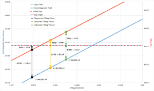
A more advanced algorithm taking into account both total magnetic field and dip angle to provide the best representation of the z-axis measurement.
In this example above the horizontal dotted line represents the reference field values for total magnetic field and dip angle. The graph has been scaled so reference values overlap for better visual representation.
The original raw measured z-axis is represented by the black line. This survey would pass standard QC values with error well within MWD QC criteria.
The yellow line represents adjusting the z-axis reading by 42 nT, to provide the same absolute error in dip angle but has improved the total magnetic field error by 36 nT.
A potential “better” solution would find the best z-axis solution . That point could possibly be represented by the green z-axis measurement.
Note: This example is for illustration purposes only and do not represent the actual algorithm used nor is it intended to make the case that SCC should be applied in this scenario. This graphic is only intended to provide an understanding of the process.
Additional Techniques
This listing is by no means comprehensive. The NISE software uses a similar method described in technique #2 for short collar correction. The algorithms embedded in NISE perform all of the hard work, users just need to check results! Switch over and save today.
Multi-Station Analysis is a more advanced survey algorithm technique designed to adjust all 3 magnetometer readings. Noralis will soon offer an automated Multi-Station Analysis solution within the software. Stay tuned for details.
For more information regarding survey corrections and general survey theory reference the ISCWSA (Industry Steering Committee on Wellbore Survey Accuracy – www.iscwsa.net, www.iscwsa.org), the free survey e-book by Angus Jamieson @ https://www.uhi.ac.uk/en/research-enterprise/wellbore-positioning-download, and also the Society of Petroleum Engineers (www.spe.org) for technical documents and case studies.
Related Features


